Warehouse loading bays
Support frequent pallet movement between a dock floor and mixed delivery vehicles.

Stationary Dock Leveler gallery
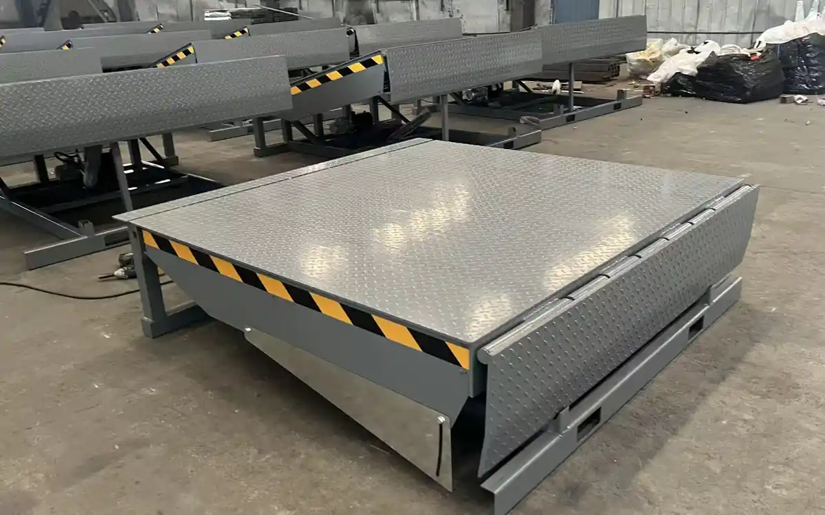
A pit-installed hydraulic bridge for repeated loading at a raised dock, compensating for the height difference between the dock floor and vehicle bed.
Choose a stationary dock leveler when trucks regularly reverse to a prepared raised dock. The platform and hinged lip bridge routine vehicle-height differences without moving equipment around the yard.
Support frequent pallet movement between a dock floor and mixed delivery vehicles.
Create a fast, repeatable transition for high-cycle inbound and outbound loading.
Connect forklifts to trucks at permanent shipping bays with a prepared pit and power supply.
A permanent raised dock and pit are available, loading is frequent, and trucks reverse to a fixed bay position.
If the forklift starts from ground level or loading positions change, use a mobile dock ramp. If the site has unusual reach or pit constraints, request a custom dock solution.
Final pit dimensions, dock height, bumper position and electrical supply must be confirmed before civil work.
| Model | Capacity | Platform size (mm) | Working range | Motor | Deck plate |
|---|---|---|---|---|---|
| HLGD-8A Reference | 8T | 2000 × 2000 | +400 / -300 mm | 1.1 kW | 6 mm |
| HLGD-8B | 8T | 2500 × 2000 | +400 / -300 mm | 1.1 kW | 6 mm |
| HLGD-8C | 8T | 3000 × 2000 | +400 / -300 mm | 1.1 kW | 6 mm |
| HLGD-10A | 10T | 2000 × 2000 | +400 / -300 mm | 1.1 kW | 8 mm |
| HLGD-10B | 10T | 2500 × 2000 | +400 / -300 mm | 1.1 kW | 8 mm |
| HLGD-10C | 10T | 3000 × 2000 | +400 / -300 mm | 1.1 kW | 8 mm |
Dimensions shown are standard references. Confirm the final platform, pit and interface drawing before construction.
Send project details →The deck, hinged lip, hydraulic power unit and pit interface form one loading-bay system that must be coordinated before installation.
Structural members carry the specified moving load across the pit opening.
The lip extends onto the vehicle bed to create the loading transition.
Push-button operation raises the platform and controls the bridge sequence.
The embedded support frame transfers load into the prepared civil structure.
Bumpers help protect the bay face; prepared steel surfaces receive an industrial coating.
Safe performance depends on the equipment, pit construction, vehicle position and operating procedure working as one system.
A mechanical support secures the raised platform during authorised service work.
Side elements help reduce exposure to the moving platform area.
Rubber bumpers help protect the dock face as vehicles reverse into position.
Warning colours identify the moving edge and loading-bay interface.
The power unit provides controlled platform and lip movement.
Patterned steel plate supports tyre grip during normal operation.
The equipment cannot be selected separately from the dock. Platform size, pit, dock face and vehicle fleet should be reviewed together.
Send project requirements →Choose between the standard 8T and 10T series using the total moving load.
Select the standard length or confirm a non-standard deck around the pit and vehicle geometry.
Coordinate pit length, width, depth, embedded frame and drainage before construction.
Confirm destination voltage, frequency, isolation and control position.
Confirm colour, bumpers, seals and site-specific bay accessories.
Equipment dimensions and the loading-bay interface are reviewed together so civil work, fabrication and installation match at delivery.
Load, vehicle, site and operating conditions are checked.
Dimensions, structure, controls and interfaces are documented.
Fabrication and functional checks follow the confirmed scope.
Shipping preparation and technical documents are arranged.
Provide total moving load, dock height, minimum and maximum vehicle floor height, bay width, loading frequency, voltage and any existing pit dimensions.
It is safer to confirm the selected model and approved pit/interface drawing before construction. Small dimensional differences can affect installation.
Calculate the combined maximum weight of the forklift, operator, attachments and cargo, then confirm the capacity with the engineering team.
The standard series uses a 1.1 kW hydraulic power unit. Voltage and frequency must be confirmed for the destination.
Standard lengths are 2000, 2500 and 3000 mm with a 2000 mm width. Non-standard requirements can be reviewed.
The complete bay may require correct pit construction, dock bumpers, vehicle-positioning measures, drainage, power isolation and operating controls.