
Heavy or concentrated loads
Engineer structure around unusual total loads, wheel loads or load distribution.
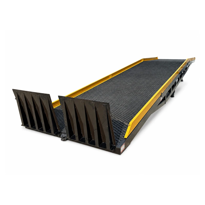 Custom Dock Solutions gallery
An engineered loading solution for unusual capacity, reach, clear width, building interfaces or operating sequences that standard dock equipment cannot resolve.
Choose a custom dock solution when capacity, geometry, civil interface or operating sequence falls outside a standard mobile ramp, dock leveler or loading platform.
Engineer structure around unusual total loads, wheel loads or load distribution.
Resolve limited approach length, unusual dock position, clearance or building constraints.
Coordinate staging, lifting, bridging, control and access protection in one loading system.
The project has a measurable constraint that changes structure, hydraulics, geometry, controls or installation interface.
Use a standard product family when ordinary capacity and dimensions meet the site; it will usually be faster to specify, build and maintain.
A custom project begins with an input register. Unconfirmed assumptions remain open until drawings and technical scope are approved.
| Design input | Information required | Why it matters | Owner | Status | Output |
|---|---|---|---|---|---|
| Load path Reference | Equipment, cargo, wheel loads | Defines structure and deck | Customer + Haolong | Required | Load basis |
| Site geometry | Photos, dimensions, clearances | Defines working envelope | Customer | Required | GA drawing |
| Vehicle interface | Floor heights, types, position | Defines bridge and reach | Customer | Required | Interface detail |
| Operating cycle | Sequence and cycles per shift | Defines hydraulics and controls | Customer + Haolong | Required | Functional description |
| Civil / power | Foundation, pit, voltage | Defines installation scope | Customer + contractor | Required | Interface schedule |
The proposal becomes reliable when load, geometry, sequence and responsibility boundaries are all documented.
Send project details →Custom dock engineering connects the load path, steel structure, hydraulic movement, controls and building interface in a single reviewed scope.
Operating, parked, transition and maintenance conditions are listed before structural selection.
Working clearances, approach angles, reach and interfaces are resolved in the general arrangement.
Frame, deck, cylinders and power unit are selected around the approved duty.
Operator actions, interlocks, stops and access protection follow the actual sequence.
Civil work, embedded parts, power, drainage and contractor responsibilities are documented.
Custom equipment requires a project-specific risk review. Safety functions must be tied to the real users, vehicles, loads and installation environment.
Working, parked, transfer, maintenance and emergency states are documented.
Guardrails, gates, barriers and exclusion zones follow the load path.
Locks, supports, chains or vehicle restraints are selected for the moving interfaces.
Required conditions are verified before hazardous movement is allowed.
Stop, lowering and recovery provisions are placed around the operating risk.
Isolation points and mechanical supports protect authorised service tasks.
The fastest route to a workable concept is a complete site pack: dimensions, loads, sequence, environment, local requirements and clear project boundaries.
Send project requirements →Engineer frame and deck around total, point and wheel loads plus the required duty.
Define working envelope, clearances, travel, slope and stowed position.
Select movement, speed, power unit, operator stations and control logic.
Coordinate guarding, gates, restraints, stops, supports and warning systems.
Document civil work, embedded parts, power, drainage, assembly and commissioning interfaces.
A custom solution progresses through requirements, concept, reviewed drawings and an agreed technical scope before production starts.
Load, vehicle, site and operating conditions are checked.
Dimensions, structure, controls and interfaces are documented.
Fabrication and functional checks follow the confirmed scope.
Shipping preparation and technical documents are arranged.
When standard equipment cannot meet the required capacity, reach, width, civil interface, vehicle mix, operating sequence or local installation constraint.
Send a dimensioned site drawing if available, wide and detailed photos, complete load data, vehicle heights, intended sequence, frequency, power supply and destination.
Photos can support an initial discussion, but critical dimensions, load data and interfaces must be measured and confirmed before final design.
Capacity is based on the actual load cases, including equipment, cargo, people, attachments, wheel or point loads and the required engineering margin.
The project should have an agreed general arrangement and technical scope before fabrication. The exact drawing package depends on the order.
Responsibilities for foundation, embedded parts, power, drainage, unloading, assembly and commissioning must be written into the project scope.